Project Idea: USB Powered LED Sign

All files for this project are attached in a zip file at the link below. These files include:
- All inventor part files: tweak to your heart’s content
- DWG Files to check tolerances
- STL files for a 3D Printer
- Laser files for the cover & Sign
- Various pictures to help with assembly
Introduction
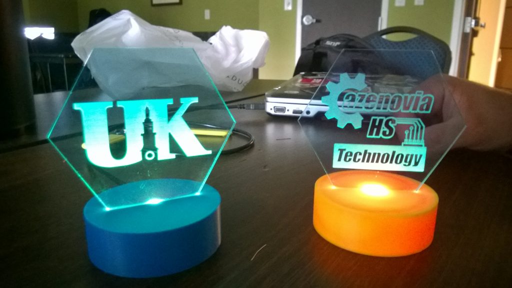
After doing an expensive LED light up sign project last year (with a grant) with my CIM students, I was
looking for a low cost alternative. In comes Scott Tobias, new CIM master teacher from Maryland. Thanks Scott for the great idea! You can make these signs for less than $3.00 apiece, depending on what you make the base out of. We 3D printed them at UK with an Affinia printer, as they were prototypes, but they could easily be CNC’d from Wax, Wood, or Renshape.
Parts List
- Male A to Male A USB Cable: Amazon
Color-changing 2 Leg LED Light:AdaFruit- Color Changing LED’s: Amazon
- 68 ohm Resistor (100 will work): Anywhere
- 1/8″ Acrylic: Delvies
The resistors are $0.05, the cable about $1.50 per end (cut the cable in half to make two!) and the LED’s about $0.50 each. That means the guts are only about $2.00 each! Great deal, and your students will love how the LED’s fade through all the colors of the rainbow, and you will love how it does it automatically, because it is built into the chip! NO PROGRAMMING or COSTLY MICROCONTROLLERS. Thanks AdaFruit! Video of how it works HERE.
 Assembly
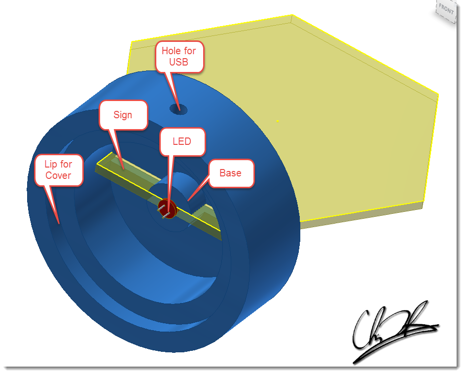
- Build the base. CNC or 3D print. Try to make sure that the LED comes in contact with the acrylic sign. Please see the enclosed Inventor Section view file for the dimensions and constraints. Also be sure to leave room in the base for all of the electronics.
- Design and build the sign. The more angles the better, as it will show off the light. Be sure to take into account the tolerance fit between the slot and the plastic. MEASURE the acrylic. It is NEVER really 0.125″!
- When engraving the sign, the deeper the engraving, the better it looks. Invert the text and print on the back!
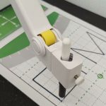
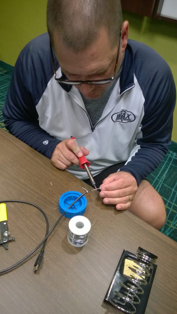
- Assemble the parts. Sign into base, wire through side, Hot glue the led into slot, THEN solder!
- Solder the cathode, short leg of LED, to the 68Ω resistor.
- Solder the resistor to the BLACK wire of the USB cable.
- Solder the RED wire to the other side of the LED. Do NOT solder the green or white wires; do not even strip them!
- When soldering, you could use heat shrink tube to prevent short circuits.
- Insert the cover into the base. We cut the cover out of the same acrylic we made the sign out of, and just made it 0.005″ bigger in Inventor, and pressed it in. The hole in the bottom is there to pry it out if necessary.
![]()