How Does PWM Work?
Question:
What is PWM, and how does it work to control a motor or any other output?
Answer:
PWM stands for Pulse Width Modulation and allows you to easily control an output in a digital system. Some things that you can control with it might be the speed of a DC motor, or the brightness of a light source. You can even use it to control the speed & direction of a constant rotation servo to drive a robot very simply.
Here’s a great video that explains how it works:
Watch the video above and see if you can answer the following questions:
- Pulse Width Modulation (PWM) is a digital signal. What is a digital signal?
- (0:57) What is the resistor for in the circuit he builds at about 0:57 of the video?
- (1:30) Why is the wave’s shape square?
- (1:40) What does a PWM signal have to do with the binary number system?
- Define duty cycle.
- (2:30) Explain how duty cycle has an affect on the average output of a PWM System
- (2:45) Explain why you cannot see the light or the motor pulse in a PWM system.
- (3:13) The circuit shown at 3:13 is used to generate a PWM signal. What kind of IC chip is used to build it?
- (3:32) Why can’t we just use a Potentiometer to vary the voltage? What might happen?
- (4:00) When using PWM to control a servo, what are the limits of the widths of the ON pulses?
- (4:40) He uses a potentiometer in the circuit. What is it used to control?
- (5:00) List the steps of the design process he used to build his circuit.
- (5:15) What is the transistor used for in this circuit?
- (8:40) What type of microcontroller was used to do the same thing?
Going Beyond:
Can you answer this question and label the signal?
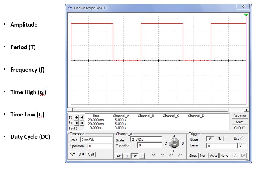
![]()