Arduino Control Systems-Block Coding

What is an Arduino / microcontroller?
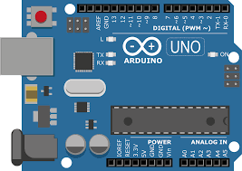
An Arduino is a microcontroller, which is a computer system on a chip that does a job. It contains an integrated processor, a small amount of memory, and programmable input/output devices, which are used to interact with things connected to the chip.
Microcontrollers can be program devices to sense temperature, detect motion, use sonar, control motors, and much more.
How does an Arduino work?
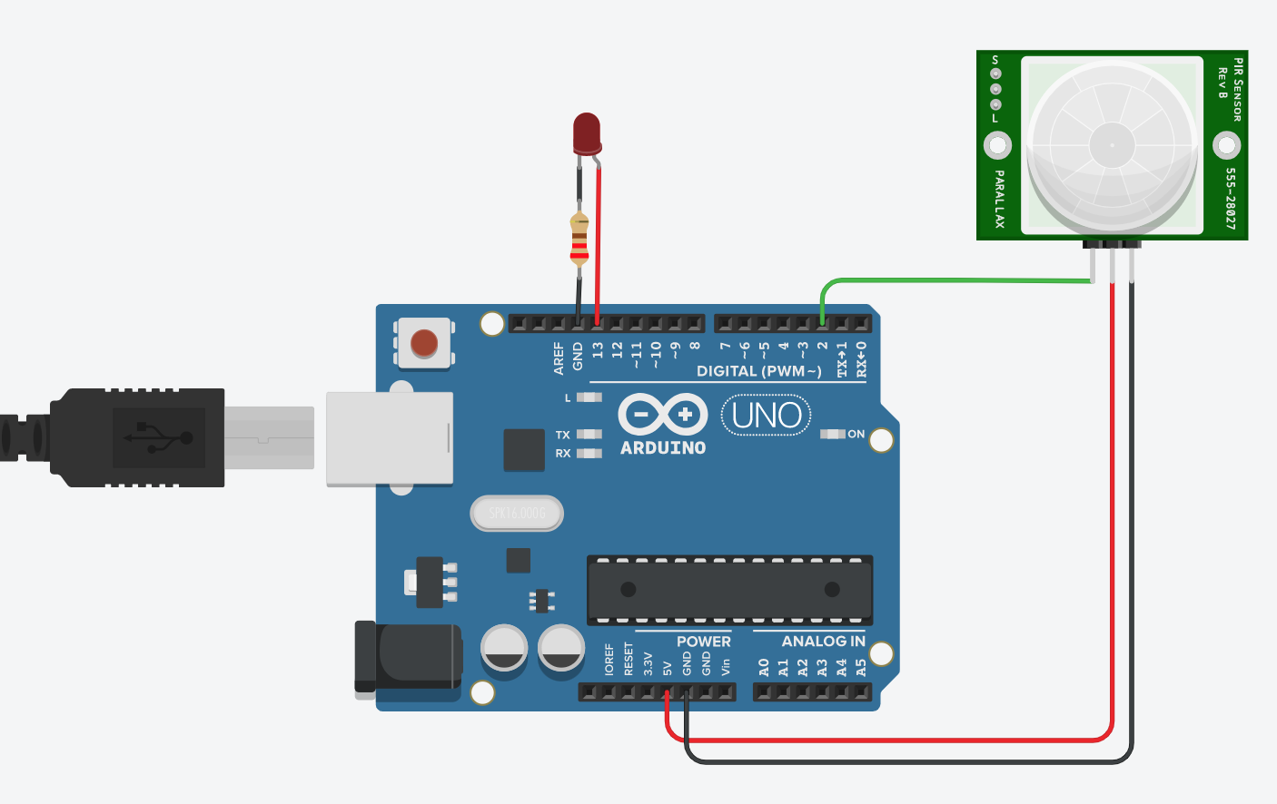
Components are connected to an Arduino. Below is an example of a motion sensor (input) and an LED (output) connected to an Arduino.
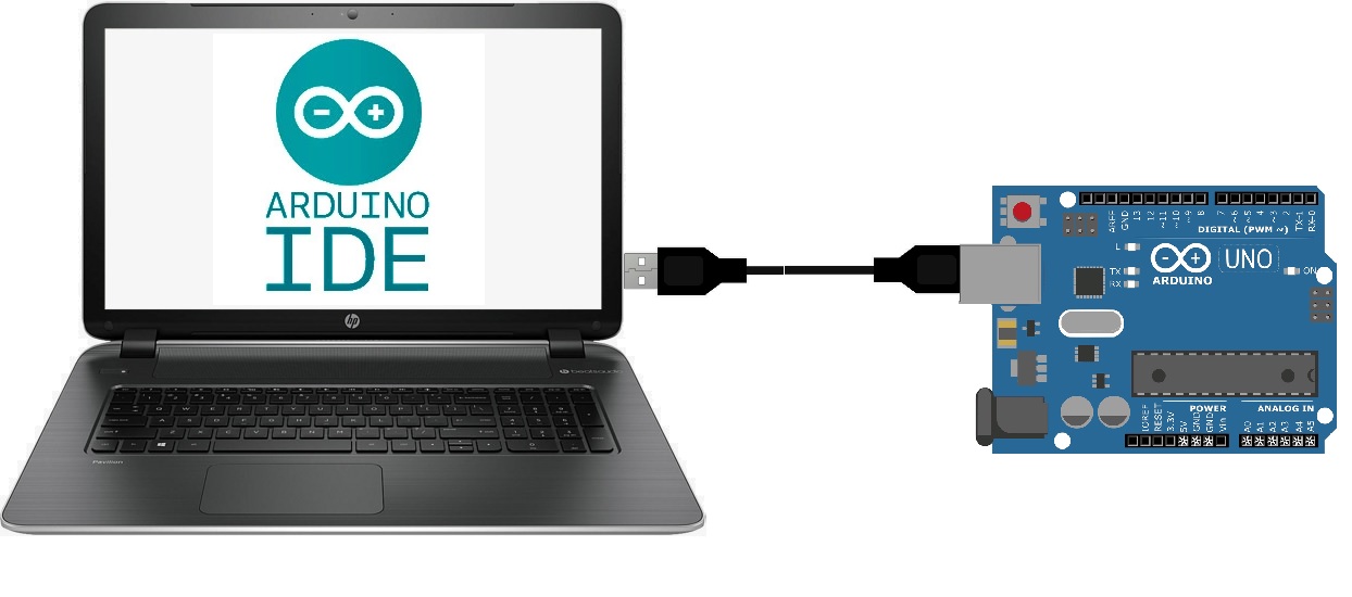
The Arduino is then connected to a computer and programmed on Arduino IDE. There is also a web version of the Arduino IDE.
Project Overview
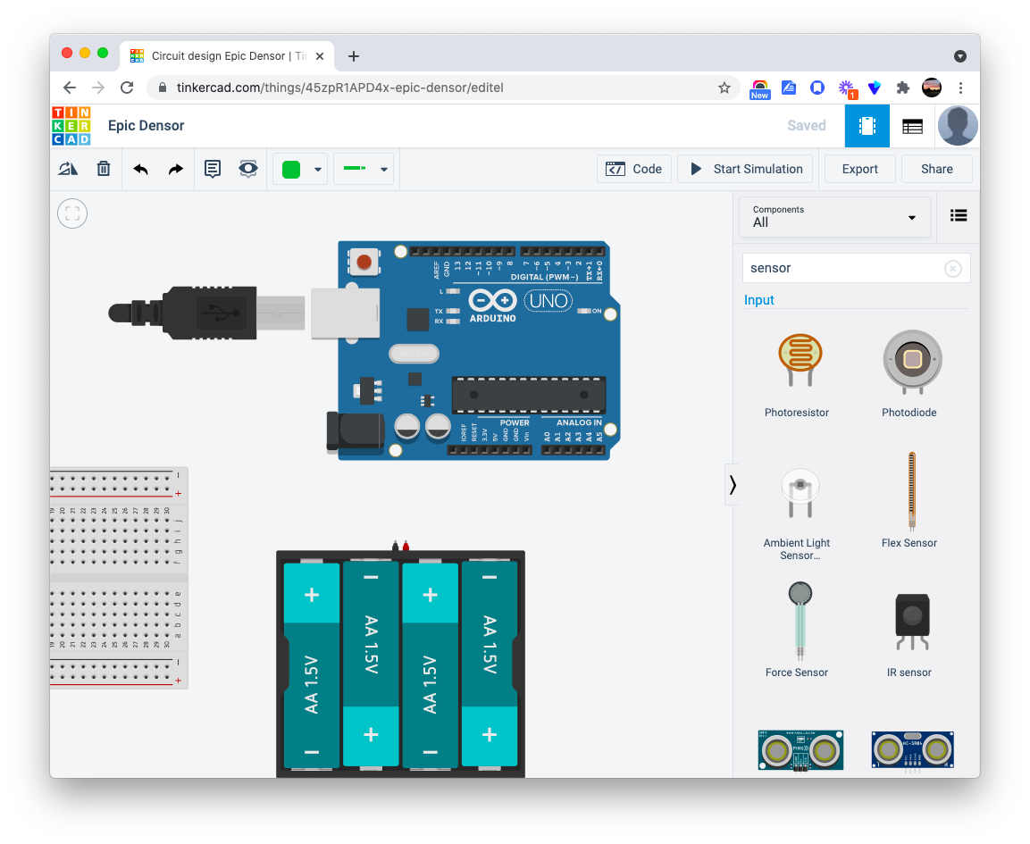
In this series, you will learn how to control input/output devices from a Arduino using Autodesk’s Tinkercad circuit simulator. This will provide hardware experience and programming experience using an Arduino, all from a website. The tutorials in this article are ideal for remote learners and beginners, and does not require coding. Each video tutorial is followed by challenges to test your knowledge and solidify concepts learned. A “turn in document” is provided to record your progress after completing each tutorial and challenge. See link below.
Special thanks to Thuc Phan, computer science and technology teacher from Cazenovia high school.
In this series you will be complete the following tasks:
Output
- Control the built-in LED on an Arduino (Digital – ON/OFF)
- Control an external LED (Digital – ON/OFF)
- Control the brightness of an LED (Analog – range of values)
- Control a servomotor (Analog – range of values)
Input & output
- Control an LED with a button
- Control a servomotor with a button
- Control an LED with a motion sensor
- Control a servomotor with a motion sensor
- Control an LED with a potentiometer
- Control a servomotor with a potentiometer
Skills Developed
| -Coding using blocks | -Working with an Arduino Uno |
| -Using TinkerCAD | -Wiring sensors |
| -PIR Motion sensor | -Resistors |
| -Buttons | -Potentiometer |
| -LEDs | -Servo motor |
| -Digital / Analog | -Inputs & Outputs |
| -Breadboards and wiring | -Troubleshooting techniques |
Hardware requirements
A computer with internet access.
Complete Playlist of Activities
Activity 1: Program the built-in LED to blink
Challenges:
- Make your LED Blink 3 times fast, pause for 4 seconds, and repeat
- Make your LED turn on for 3 seconds, turn off for 1 second, and repeat
Activity 2: Program an external LED to blink
Challenges:
- Make an external LED blink SOS in morse code. 1 second on represents a dot. 3 seconds on represent a dash. Add a 1 second delay between each dot or dash within the same letter. Add a 3 second delay between each letter.
- Make an external LED blink a 5 letter word in morse code.
- Make two LEDs blink alternately on and off. LED on for 1 second, off for 1 second, and repeat. As LED 1 is on, LED 2 is off and the other way around. [Circuit]
Activity 3: Learn to Loop or Repeat a Program
Challenges:
- Using a repeat block, make an external LED blink 10 times, remain on for 10 seconds, and then repeat.
- Create a circuit with two LEDs. Using repeat blocks, make the two LEDs alternately blink 10 times and then repeat.
Activity 4: Adjust the Brightness of an LED
Challenges:
- Make an LED increase in brightness in increments of 50 from 0 to 250 then decrease in brightness in increments of 50 from 0 to 250. Set a delay of 2 seconds for each change in brightness.
- Create a circuit with 2 LEDs. Make the 2 LEDs increase and decrease in brightness alternately using the criteria above. As LED1 is increasing in brightness, LED2 should be decreasing in brightness, then as LED1 decreases in brightness, LED2 should be increasing in brightness. Each change in brightness should be in increments of 50 from 0 to 250 and 0 to 250. Set a delay of 2 seconds for each change in brightness.
Activity 5: Control a Servo Motor
Challenge:
- Make a servo motor pan from 80 to 100 and 100 to 80 in increments of 5.
Activity 6: Control an LED with a Button
Challenges:
- Make a circuit with 2 buttons and 2 LEDs. Assign each button to an LED.
When button 1 is held down, LED1 should turn ON
When button 2 is held down, LED2 should turn ON
When neither buttons are held, both LEDs are OFF - Make a circuit with 5 buttons and 1 LED. Assign each button to turn on the LED at a specific brightness.
If button 1 is held, the LED brightness = 50
If button 2 is held, the LED brightness = 100
If button 3 is held, the LED brightness = 150
If button 4 is held, the LED brightness = 200
If button 5 is held, the LED brightness = 250
If button no buttons are pressed, the LED is off
Activity 7: Control a Servo Motor with a Button
Challenges:
- Make a circuit with 1 button and 1 servo. When the button is held down, set the servo to 180. When the button is not pressed, set the servo to 0.
- Make a circuit with 5 buttons and 1 servo. Assign each button to specific servo positions.
When button 1 is pressed, set the servo position to 0 When button 2 is pressed, set the servo position to 45
When button 3 is pressed, set the servo position to 90 When button 4 is pressed, set the servo position to 135
When button 5 is pressed, set the servo position to 180
Activity 8: Control an LED with a Motion (PIR) Detector
Challenge:
- Make a circuit with 1 PIR sensor and 1 LED. Make the LED blink SOS in morse code when the PIR senses movement. The LED is OFF when there is no movement.
Activity 9: Control a Servo Motor with a Motion (PIR) Detector
Challenge:
- Make a circuit with 1 PIR sensor and 1 servo motor. Set the servo to move back and forth from 0 to 180 and 180 to 0, and loop when the PIR senses movement. Set the servo position back to 0 when there is no movement.
Activity 10: Control the Brightness of an LED with a Potentiometer
Challenge:
- Make a circuit with 3 potentiometers and 3 LEDs. Assign each potentiometer to an LED and make each potentiometer control the brightness of its assigned LED. Each of the potentiometers should control each of the LEDs’ brightness from 0-255.
Activity 11: Control a Servo Motor with a Potentiometer
Challenge:
- Make a circuit with 3 potentiometers and 3 servo motors. Assign each potentiometer to a servo motor and make each potentiometer control the position of its assigned motor. Each of the potentiometers should control each of the servo motors’ position from 0-180.
Going Beyond
Project Option #1 – From Simulation to Real World (Hardware)
Building TinkerCAD circuits in real life. Below is a 2 minute video on how to transfer a TinkerCAD circuit to a an Arduino.
Try using other components….
Purchasing Hardware
Buying the Microcontroller: There are many types of Arduino boards. The one covered mostly in this article refers to the Arduino UNO R3 and can be purchased on Amazon.com for less than $20. (Just keep in mind that you will need a USB-A to USB-B that is not included). There are also other brands such as Elegoo that make microcontrollers that function exactly the same and that are cheaper. Elegoo UNO R3
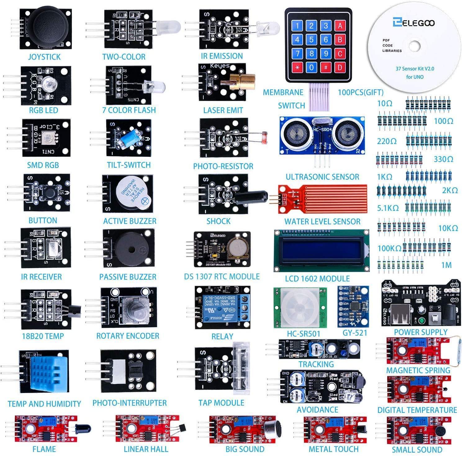
Buying Input/Output Components: Here are some kits that you can buy from Amazon.com
- 37 Sensors kit
- Starter kit with motors, sensors, wires, etc. Microcontroller included
- Arduino Robot Car
Project Option #2 – Robotic Arm (Hardware)
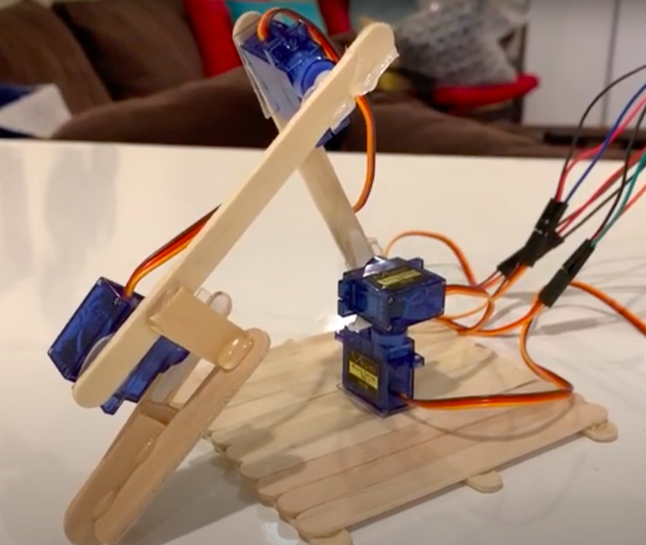 | Robotic arms can be found in many industries including manufacturing. They can be used to conduct processes and operations such as welding, painting, transporting, packaging, and more. Robotic arms can aid in executing repetitive movements and have human-like dexterity. Each axis joint on a robotic arm can be rotated with a servo motor and can be referred to as the waist, shoulder, and elbow. |
Purchasing Hardware
- Mini Servo motors
- Potentiometers
Project Option #3 – Data Acquisition
 https://www.shutterstock.com/ https://www.shutterstock.com/ | Sensors and data acquisition play a very important role in all areas of science, technology and engineering. Temperature sensors work to keep the homes we live in the temperature that we like, light sensors are used to determine a satellite’s position in regards to the sun, and all of this data has to be saved, manipulated or processed, and then analyzed to make well informed decisions. |
Less Technical Option
Tools needed: a smartphone with the Science Journal app: science-journal.arduino.cc
More Technical Option
Buying the Microcontroller: A great alternative to the Arduino UNO is the Arduino Nano 33 BLE Sense which is about $33. This microcontroller is smaller but features Bluetooth connectivity and built-in sensors temperature, pressure, humidity, light, color and gesture sensors, and more.
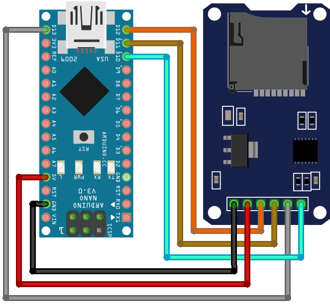
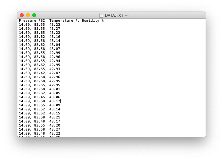
Buying the Data Logger: This is a module connects to a microcontroller and records data to an SD card. This sd card module can be purchased on Amazon.com for less that $10.
Building the circuit: This is not a circuit you can simulate in tinkerCAD.com. Below is how to wire these together:
Resources:
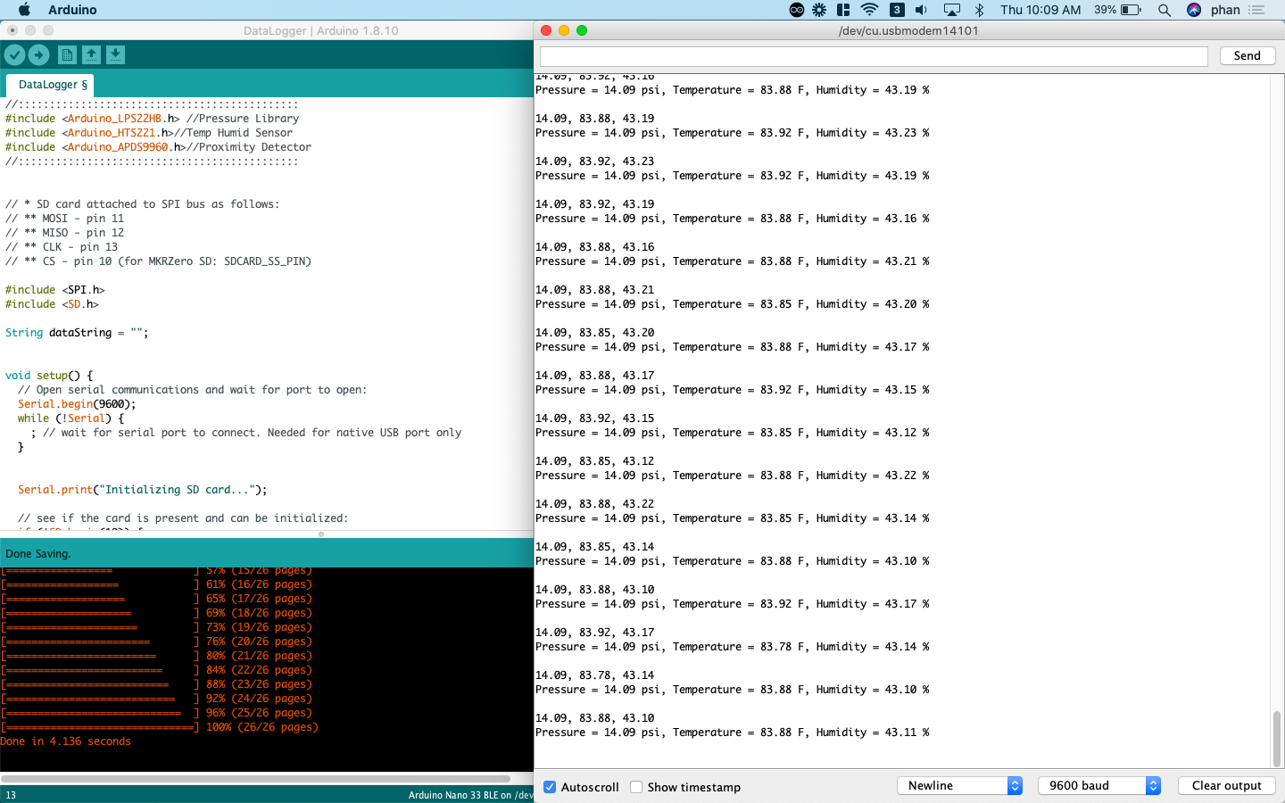
- Here is the Arduino sketch (modified by Phan/Hurd)
- Troubleshooting Power – 5v pin on the Arduino Nano 33 BLE Sense
- Logging data from Arduino to SD documentation
- Logging data from Arduino Nano to SD documentation
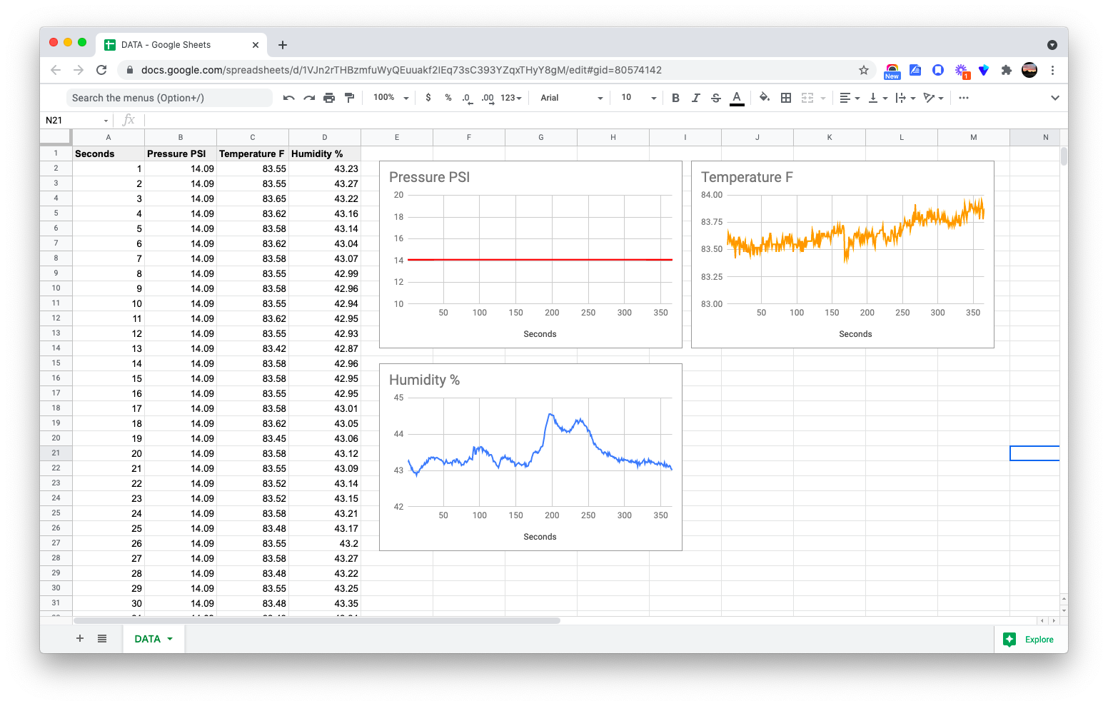
Results:
Going Further Beyond
Here is an example of students sending HD video cameras and sensors into the stratosphere with a weather balloon.
![]()