Tag: servo
Question:
What is PWM, and how does it work to control a motor or any other output?
Answer:
PWM stands for Pulse Width Modulation and allows you to easily control an output in a digital system. Some things that you can control with it might be the speed of a DC motor, or the brightness...
Dobot to Dobot Handshake!
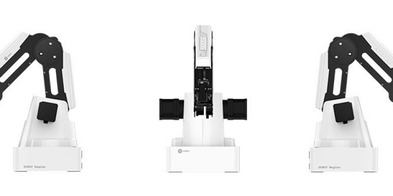
We did it! We made a dobot magician talk to another one and make it start. We even added a VEX switch as an input to start the first one. It is easy to do, but one word of caution:
Never connect or disconnect any wires to the dobot while it is powered on; always power it down first. Damage may result!
Ok,...
The Lynxmotion AL5D V2: Putting it all together
So you have new Lynxmotion robots for your classroom, so now you have to build and wire them. I’ve put together 4 videos to help you assemble and wire them. This is not meant to replace the manual, but rather to supplement it. You can find the manual here: PLTW-AL5D-Guide-11. Lots of new...
Centering Servos
Question:
How do you center the servos when you build your lynxmotion AL5D?
Answer:
Best way is to NOT turn the servos; like that’ll happen! There is a whole section in the new manual that can help you teach how servos work, so check the manual too! You can find it here: PLTW-AL5D-Guide-11. One...
How do you use outputs on a Dobot Magician?
Question:
How do you use outputs on a Dobot Magician to do something?
Answer:
How about a grinding operation? See below for the basics. A full blown tutorial will be coming soon!
A Grinding Operation with the Dobot and a Continuous Rotation Servo
This robot is the smoothest, speediest, most accurate...
Feetech Servo on the Lynxmotion AL5D Arm
Question:
My new Lynxmotion AL5D robot arm from RobotShop came with a new servo called a Feetech. How come my arm works backwards now?
Answer:
Well…. because the servo may be installed backwards. I know, you looked at the picture on the directions, but the first one may be wrong. When they...
HOW DO YOU FIX A SERVO WITH STRIPPED GEARS?
Question:
How do you fix a wrist rotate servo with stripped gears? It’s a pain in the butt as well as costly to replace.
Answer:
See the steps below for an inexpensive and simple solution! Note that te metal gears cost almost as much as the servo; it takes 5-10 minutes to change the gears,...
MY SHOULDER SERVO IS BURNED OUT AND THEY NO LONGER MAKE IT. WHAT DO I DO NOW?
Problem:
This post is ARCHIVED, meaning links may or may not work, and it may not scale well on a mobile device as it was written a while ago.
My shoulder servo doesn’t work anymore, and I’m told they don’t make this servo anymore. What do I do now?
Solution:
You could cry, but...
HOW DO I MAKE SURE MY SERVOS ARE CENTERED?
Question:
How do I make sure my servos are centered before I build my robot? How can I test my servos once it is built?
Answer:
The I.L.A.R. (It Looks About Right) method works ok, but if you want to be precise, you need a servo driver. This video shows you how to use one to test your servos. One...


